bemo-cofra banner
space

Issue #2 - Published by the BEMO-COFRA Project – February, 2013

space
space space
space

First Year DEMO

space
space

A demonstrator showing some aspects of the BEMO-COFRA system was created for the 1st year review. The demo also serves as a vehicle for testing the integrated components in a more complete scenario.

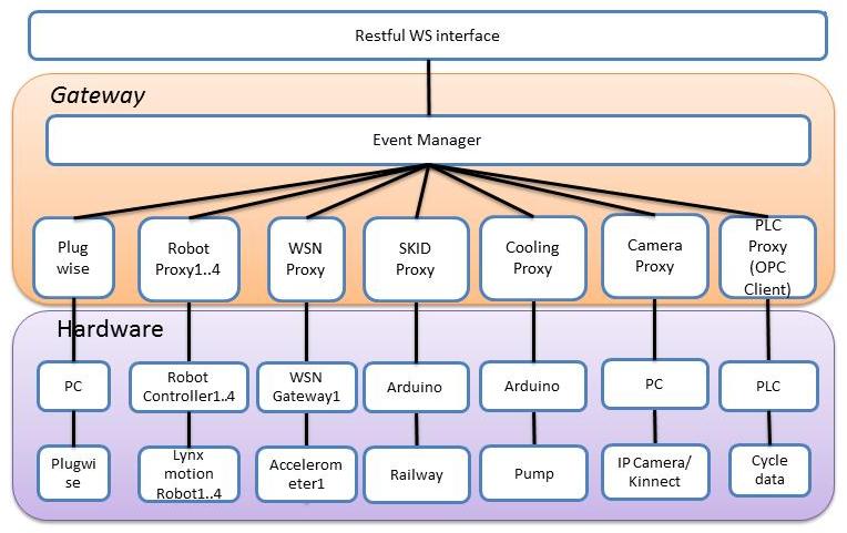
The main components in this prototype are described in Figure 1 below. The hardware level contains the drivers for the integrated hardware devices. At the gateway level we find the LinkSmart components such as the Event Manager and also newly developed LinkSmart proxies which interact with the different hardware drivers.

The LinkSmart proxies make the devices known in the LinkSmart network and provide services that can be invoked from different applications. Furthermore LinkSmart provides basic communication in the prototype such as service discovery and eventing. The eventing of LinkSmart is a simple publish/subscribe model that is based on topics. More information regarding LinkSmart can be found on the HYDRA project's website(LINKSMART, 2012) as well as here (LINKSMART, 2012).

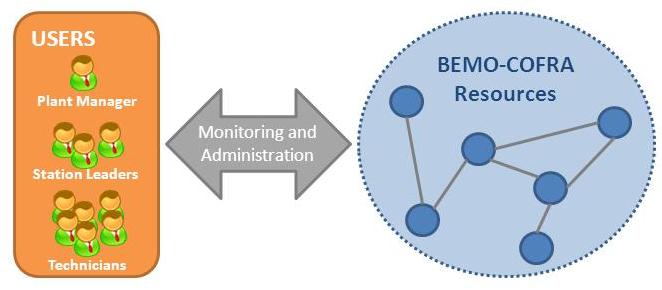
In order to test these components they have been deployed in the month 12 demo. The M12 demo is based on the scenario in Figure 2.

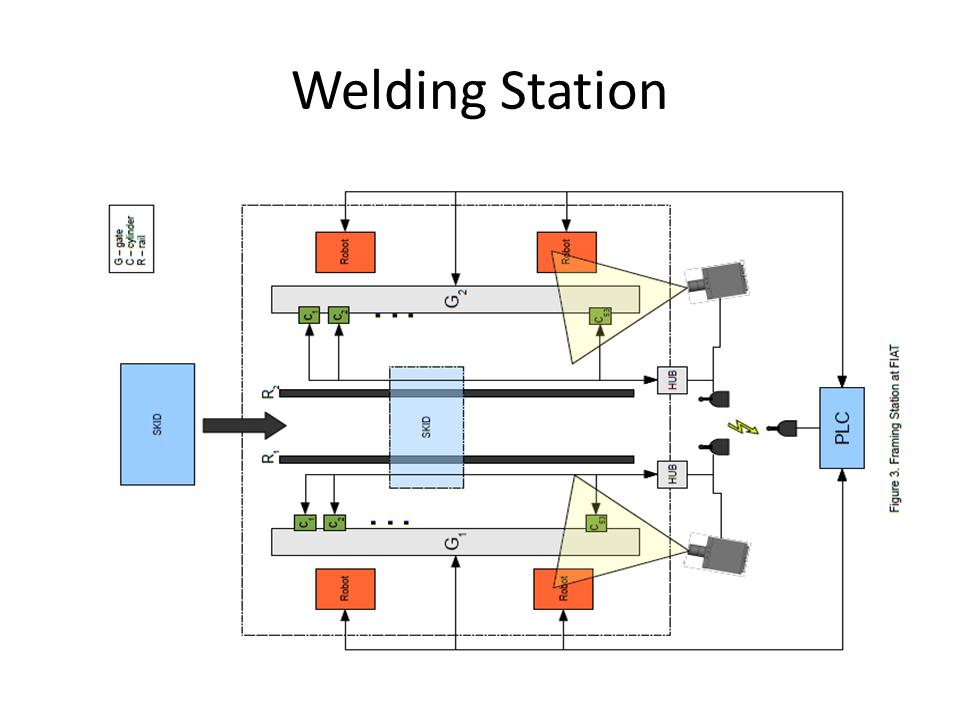
The scenario involves a welding station where car body parts arrive on a skid to be welded. This welding station contains a number of different devices:

• SKID : structure that carries the car body;

• Rail: The SKID moves under two rails that have a specific code for positioning. This code is read while the SKID is sliding inside the Cell;

• Gate: Devices locking the SKID with the car body after it is correctly positioned into the Cell. There are two of them to lock the two lateral parts of the car body;

• Cylinder: A cylinder is a component of a clip. The clips are responsible for locking the car body before the robots start the welding operation. Each cylinder has two sensors, indicating the status of that cylinder. For example, a cylinder has a sensor indicating an open state and a sensor indicating a closed state. There are 53 cylinders for each gate, or equivalently, 106 sensors;

• Robot: The robots doing the actual welding;

• Hub: The state of each sensor is linked through a wire to a hub composed of 8 devices with 16 inputs. The state of each sensor can be transmitted to a PLC through a wireless link;

• PLC: Device that commands all the operations in the cell, regarding, for example the gates, the movement of SKID and the clips.

Simulation

The actual M12 demo is a simulation of a subset of the welding station scenario with some devices simulated, see Figure 3.

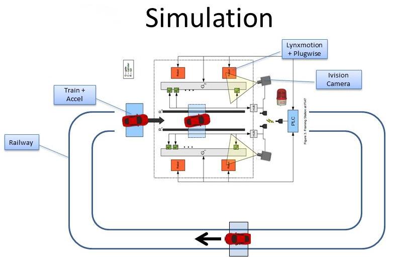
The SKID is simulated by a train that can be controlled through software. The robots are not actual welding robots but are controllable “hobby” robots. The PLC and the vision system are not simulated but are the same as in the scenario.

The M12 demo uses the following steps:

• PLC runs a simplified framing station cycle

o PLC waits until a car is in the station

• A car is entering the framing station

o Use magnetic sensor to identify a car is in the station

• Stop the SKID (train)

o PLC cycle progresses & waits for position sensors to confirm

• Sensor checks the position of the body

o If the position is ok, publish ”event_frame_pos_ok“,

 Set variable in OPC, PLC runs the cycle further (step progresses)

 PLC proxy publish “event_start_welding_event” (or the steps)

o If the position is not ok, publish ”event_frame_pos_error“,

 variable in OPC, PLC runs the cycle further

• Pneumatic gripper(s) lock the SKID

o Set variable in OPC, Step cycle progresses

• Lynxmotion robots wait for „event_start_welding_event”

o Robots move for a couple of seconds simulating a welding process

o Show energy consumption of the robots

• Robots finish the welding process

o Robot proxies raise an event “event_finished_welding_event” and PLC Proxy set variable in OPC

• Pneumatic gripper(s) Unlock the SKID

• Run the SKID (train) forward until it gets back into the station again.

The picture below shows the actual setup of demonstrator during the review showing the robots, skid with car, vision system with mounted lamp and if one looks carefully one of the wireless sensors is visible just by the right robot.

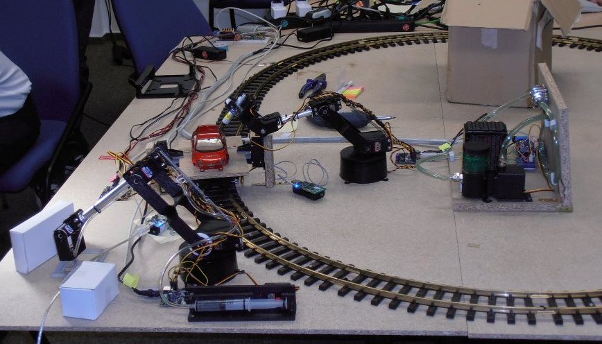
At the M12 review the prototype was demonstrated with good results showing the different components working together but also showing that partners located in very different parts of the world can cooperate in creating the demonstrator.

to the top to top
space
space space
 

The Initial BEMO-COFRA Administration Tool

 
space
One of the objectives of BEMO-COFRA is to develop a protocol for monitoring and control of wireless sensor and actuator networks (WSANs) and to implement an administration tool for WSANs. The administration tool will allow users to only view data that is relevant to their specific needs and demands

The figure below shows the various users that use the BEMO-COFRA system to monitor and administer different parameters of the production line.

A number of requirements for the administration and monitoring tool have previously been identified and analysed. These requirements include:

• Visualization of the high level state of the system

• Visualization of network management and resource monitoring data of the WSAN

• Enable notifications to the user

• Allow setting of WSAN parameters

• Running on a portable device (Mobile phone/Tablet).

The first demo of the BEMO-COFRA platform included an initial prototype of the administration and monitoring tool which supported the visualization of BEMO-COFRA resources in real-time together with additional information. This initial prototype focused on defining the technical basis for the implementation of the final version which will be developed during the next 12 months of the project.

Architecture

The administration tool consists of three elements, the Web Service Client, the Event Processing and the GUI Engine.

The Web Service Client is used to connect with the BEMO-COFRA environment through the Event Manager of the LinkSmart platform. It subscribes to the events of interest and passes them on to the Event Processing.

The Event Processing unit creates a new object instance to represent new resources, if an event comes from a resource that is not known by the administration tool yet. In all other cases the current state of the resource representation is updated according the received events.

Finally the visualization of the BEMO-COFRA environment is generated by the GUI Engine that is responsible for the interaction with the user.

Background Research

The development of the initial administration and monitoring tool for the BEMO-COFRA system required some background research into existing platforms that could be used for the implementation of the administration tool. Thus a survey was conducted into the following existing platforms: Android, iOS, Windows Phone, and Windows 8 / Windows RT. In addition, research into a variety of tools available for monitoring wireless sensor networks that can be used to set the baseline for the administration tool were made. These include: Z-monitor, 6PANview, Nagios, Mango, Zenoss, and Hyperic HQ.

In conclusion from the research into existing platforms and tool, the BEMO-COFRA administration tool will be based on a simplified browser-based interface as it is widely accepted format used by the existing monitoring tools. In addition, to present e.g. a 3D representation of the high-level system state, a standalone version must be supported on the main mobile and desktop platforms. This requirement suggests the usage of a platform-independent framework that introduces minimal code porting overhead.

In order to achieve a maximum of supported platforms the administration tool is implemented with Unity3D and can be run on Android, iOS, Windows and as web application.

The Next Steps

Upcoming work for the administration tool will focus on two aspects, which are (1) enabling viewing of information at different levels of detail for different users and (2) integrating the monitoring and administration protocol into the tool. This will provide the relevant stakeholders with additional in-depth data of the Wireless Sensor and Actuator Network components of the BEMO-COFRA environment.

to the top to top
space
space space
 

The Initial BEMO-COFRA Network Architecture

 
space
BEMO-COFRA has conducted a survey of the state of the art in robotics and sensor integration with the aim to provide information on devices, services, standards, systems and applications currently adopted within the application domain relevant to the BEMO-COFRA project.

The survey allowed the project team to identify the basis for the definition of the legacy section of the BEMO-COFRA architecture. Concentration on the welding process (which is the focus of BEMO-COFRA’s user scenario), the survey included a description of the current status of the automotive manufacturing robots, its communication systems, the role of sensors/controlling systems at COMAU´s factory floor, and of the modern technology of Wireless Sensor Networks and its integration with robots. The welding process is one of the most important elements in automotive manufacturing and where problems such as signal loss are likely to occur.

Single-radio WSAN Networks

In the context of single-radio single-channel WSAN networks, efforts were made towards a smart management of the network. Moreover, the focus was to provide a policy-based solution that aimed to make a network that is capable of reacting to a set of pre-defined contexts as well as facilitate monitoring activities. In other words, topologies' changes could be enforced as a reaction to these undesirable situations set by the system administrator. Also, users of the system would be able to subscribe to these undesirable situations, so as to be notified when one of them happens.

A 6LowPan stack was used along with RPL as the routing protocol. In the 6LoWPAN based WSAN, nodes could play the role of a sink or a sender. The sink node was responsible for exchanging data between the 6LoWPAN network and the application server while the sender nodes were actively gathering data from their sensors and sending to the application server.

The application server, in its turn, processes sender node’s data, in order to evaluate both the state of the nodes’ sensors (i.e. temperature, accelerometer and so on) and the network’s state (i.e. which node is connected to which node and so on). Provided that it receives the data from all the node’s network, the system could analyse whether one of the contexts were met. Subsequently, notifying the subscribers of the context and executing commands to enforce topologies changes by making the use of RPL’s metrics/restrictions.

As a result of the research, the project team now has better knowledge of the type of technologies and systems relevant for the development of the BEMO-CORRA network architecture.

to the top to top
space
space

space
space
header bg

You're receiving this newsletter because you have been in contact with one or more of the BEMO-COFRA partners.

We thought you might be interested in following the progress of the project.

Copyright the BEMO-COFRA team © 2013 - Please feel free to quote the content in this newsletter.

Please also see our Legal Notice for disclaimers and rights.

Having trouble reading this? View it in your browser. Not interested? Unsubscribe instantly.